New Keyboard Shield
This guide will walk through the steps necessary to add ZMK support for a keyboard that uses an add-on MCU board (e.g. Pro Micro compatible) to provide the microprocessor.
The high level steps are:
- Create a new ZMK module to contain your shield.
- Create a new shield directory.
- Add the base Kconfig files.
- Add the shield overlay file defining:
- The keyboard scan driver for detecting key press/release.
- The matrix transform for mapping keyboard scan row/column values to key positions in the keymap.
- The physical layout definition to select the matrix transform and keyboard scan instance.
- Add a default keymap, which users can override in their own configs as needed.
- Add a
<my_shield>.zmk.ymlmetadata file to document the high level details of your shield, and the features it supports.
Many of the above files will differ depending on whether your keyboard is a unibody or is split into multiple parts.
After adding ZMK support for a basic shield using this guide, check the sidebar for guides on adding any additional features (such as encoders) that your keyboard has. It may be helpful to review the upstream shields documentation to get a proper understanding of the underlying system before continuing.
When writing your shield, please be aware of licensing:
- If you reference code or other items that are under a copyleft license (e.g. GNU GPLv2, used by QMK) as a reference, you must license your shield under a compatible copyleft license.
- If you license anything under a copyleft license, it cannot be referenced by anyone working on ZMK (see our clean room policy).
We generally recommend licensing your shield under MIT, if you don't have a particular incentive to do otherwise.
New ZMK Module Repository
The first step to creating the shield is to create a new ZMK module repository from a template.
This guide assumes you already have a configured GitHub account. If you don't yet have one, go ahead and sign up before continuing.
Follow these steps to create your new repository:
- Visit https://github.com/zmkfirmware/unified-zmk-config-template
- Click the green "Use this template" button
- In the drop down that opens, click "Use this template".
- In the following screen, provide the following information:
- A repository name, e.g.
my-shield-module. - A brief description, e.g.
ZMK Support For MyShield Keyboard. - Select Public or Private, depending on your preference.
- A repository name, e.g.
- Click the green "Create repository" button
The repository is a combination of the directories and files required of a ZMK config, and those required of a shield module. This enables the use of GitHub Actions to test that the shield is defined correctly. See also the page on module creation for a reference on exactly which file structure and files are required for a ZMK keyboard module.
We recommend that you take this moment to name your module according to our convention, i.e. your zephyr/module.yml file should begin with
name: zmk-keyboard-<keyboard_name>
New Shield Directory
Shields in Zephyr module "board root" go into the boards/shields/ directory; that means the new shield directory in your module repository should be:
mkdir boards/shields/<keyboard_name>
Base Kconfig Files
You can check out the shields folder in the ZMK repo that houses the in-tree supported shields in order to copy and modify as a starting point.
There are two required Kconfig files that need to be created for your new keyboard shield to get it picked up for ZMK, Kconfig.shield and Kconfig.defconfig.
All file names are case sensitive.
- Unibody Keyboard
- Split Keyboard
Kconfig.shield
The Kconfig.shield file defines the shield name used to build your keyboard.
- Unibody Keyboard
- Split Keyboard
# No whitespace after the comma or in your keyboard name!
config SHIELD_MY_KEYBOARD
    def_bool $(shields_list_contains,my_keyboard)
This will set the SHIELD_MY_KEYBOARD flag to y whenever my_keyboard is used as the shield name.
The SHIELD_MY_KEYBOARD flag will be used in Kconfig.defconfig to set other properties about your shield, so make sure that they match.
Split keyboards have multiple shield names defined, one for each part.
For example, if your keyboard consists of two halves named my_keyboard_left and my_keyboard_right, it would look like this:
# No whitespace after the comma or in your part name!
config SHIELD_MY_KEYBOARD_LEFT
    def_bool $(shields_list_contains,my_keyboard_left)

# No whitespace after the comma or in your part name!
config SHIELD_MY_KEYBOARD_RIGHT
    def_bool $(shields_list_contains,my_keyboard_right)
This will set the SHIELD_MY_KEYBOARD_LEFT flag to y whenever my_keyboard_left is used as the shield name.
Likewise, when my_keyboard_right is used as the shield name the SHIELD_MY_KEYBOARD_RIGHT flag is set to y.
The SHIELD_MY_KEYBOARD_LEFT and SHIELD_MY_KEYBOARD_RIGHT flags will be used in Kconfig.defconfig to set other properties about your shields, so make sure that they match.
ZMK supports split keyboards with more than two parts, repeat the above for each part of your keyboard.
Split keyboards with more than two parts
For split keyboards with more than two parts, you can define additional flags for each part of your keyboard. Each keyboard part should have a unique shield name. For example:
# No whitespace after the comma or in your part name!
config SHIELD_MY_KEYBOARD_LEFT
    def_bool $(shields_list_contains,my_keyboard_left)

# No whitespace after the comma or in your part name!
config SHIELD_MY_KEYBOARD_RIGHT
    def_bool $(shields_list_contains,my_keyboard_right)

# No whitespace after the comma or in your part name!
config SHIELD_MY_KEYBOARD_NUMPAD
    def_bool $(shields_list_contains,my_keyboard_numpad)
Kconfig.defconfig
The Kconfig.defconfig file is used to set new defaults for configuration settings when this shield is used.
One main item that usually has a new default value set here is the ZMK_KEYBOARD_NAME value, which controls the display name of the device over USB and BLE.
The updated new default values should always be wrapped inside a conditional on the shield config name defined in the Kconfig.shield file.
- Unibody Keyboard
- Split Keyboard
if SHIELD_MY_KEYBOARD

# Name must be less than 16 characters long!
config ZMK_KEYBOARD_NAME
    default "My Keyboard"

endif
For split keyboards, a central side (usually the left) is specified via the configuration in this file. For that side, the keyboard name is assigned and the central config is set. The peripheral side is not assigned a name. Finally, the split config needs to be set for both sides:
if SHIELD_MY_KEYBOARD_LEFT

# Name must be less than 16 characters long!
config ZMK_KEYBOARD_NAME
    default "My Keyboard"

config ZMK_SPLIT_ROLE_CENTRAL
    default y

endif

if SHIELD_MY_KEYBOARD_LEFT || SHIELD_MY_KEYBOARD_RIGHT

config ZMK_SPLIT
    default y

endif
Split keyboards with more than two parts
For split keyboards with more than two parts, adjust the number of peripheral parts and BLE connection settings:
if SHIELD_MY_KEYBOARD_LEFT

# Name must be less than 16 characters long!
config ZMK_KEYBOARD_NAME
    default "My Keyboard"

config ZMK_SPLIT_ROLE_CENTRAL
    default y

# If not set, the default is 1 peripheral part
# Set to the number of peripheral parts in your split keyboard
config ZMK_SPLIT_BLE_CENTRAL_PERIPHERALS
    default 2

# Set this to ZMK_SPLIT_BLE_CENTRAL_PERIPHERALS + your desired number of BT profiles (default is 5)
config BT_MAX_CONN
    default 7

# Set this to the same number as BT_MAX_CONN
config BT_MAX_PAIRED
    default 7

endif

# List all Kconfig flags for each part of your split keyboard here, e.g.:
if SHIELD_MY_KEYBOARD_LEFT || SHIELD_MY_KEYBOARD_RIGHT || SHIELD_MY_KEYBOARD_NUMPAD

config ZMK_SPLIT
    default y

endif
User Configuration Files
In addition to the Kconfig.shield and Kconfig.defconfig files, many shields will also define a user configuration file called my_keyboard.conf.
This file exists to provide "suggestions" of configuration settings for a user to select, such as enabling deep sleep.
Note that the name should match the shield/part name defined in the Kconfig.shield file.
This file can also be used to set configuration options. However, if a flag is set in this file, the user can no longer change it. Though sometimes necessary, this method of setting configuration options is discouraged. The case for which this is necessary is due to be eliminated in the future, making this method redundant.
- Unibody Keyboard
- Split Keyboard
Split keyboards can have multiple .conf files, one for each part. For example:
my_keyboard.conf- Configuration elements affect both halvesmy_keyboard_left.conf- Configuration elements only affect left halfmy_keyboard_right.conf- Configuration elements only affect right half
In most case you'll only need to use the .conf file that affects both halves of a split board.
The shared configuration in my_keyboard.conf is only applied when you are building with a zmk-config folder and it is present at config/my_keyboard.conf.
Shield Overlays
- Unibody Keyboard
- Split Keyboard
Shield overlay files contain a devicetree description that is merged with the primary board devicetree description during the firmware building process. There are three main things that need to be defined in this file:
- Your keyboard scan (kscan) driver, which determines which GPIO pins to scan for key press events
- Your matrix transform, which acts as a "bridge" between the kscan and the keymap
- Your physical layout, which aggregates the above and (optionally) defines physical key positions so that the keyboard can be used with ZMK Studio.
- Unibody Keyboard
- Split Keyboard
A unibody keyboard will have a single overlay file named my_keyboard.overlay, where my_keyboard is the shield name defined in the Kconfig.shield file.
A split keyboard will have an overlay file defined for each split part. For example, if the keyboard is split into a left and a right half, these can be named:
my_keyboard_left.overlaymy_keyboard_right.overlay
Here my_keyboard_left and my_keyboard_right are the shield names defined in the Kconfig.shield file.
Split keyboards often share some of their devicetree description.
The standard approach is to have a core my_keyboard.dtsi (devicetree include) file, which is included into each of the shield overlays.
Kscan
The kscan node defines the controller GPIO pins that are used to scan for key press and release events. The pins are referred to using the GPIO labels noted in the pinouts below:
- Arduino Uno Rev3 Shields
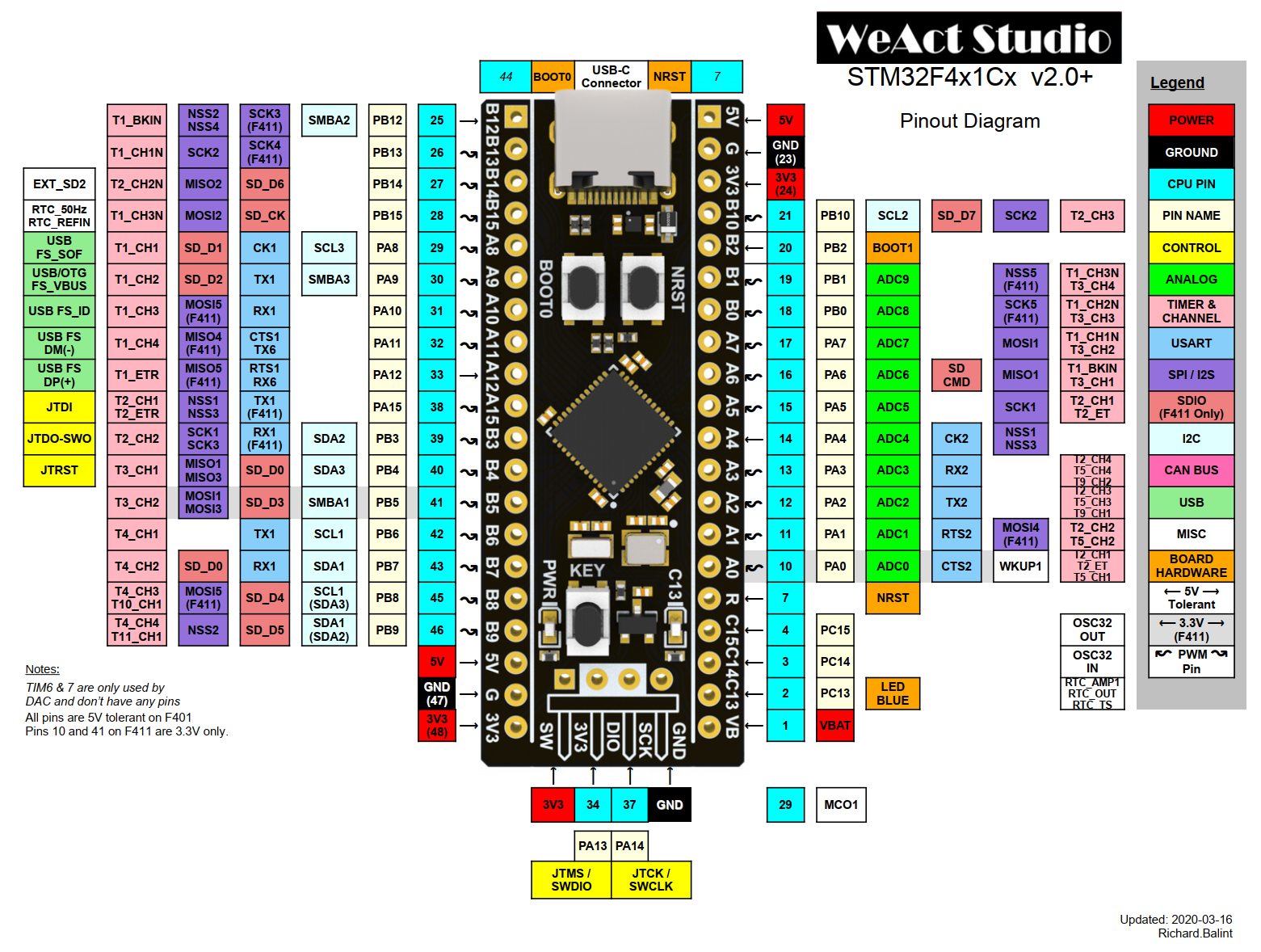
- BlackPill Shields
- Pro Micro Shields
- Seeed XIAO Shields
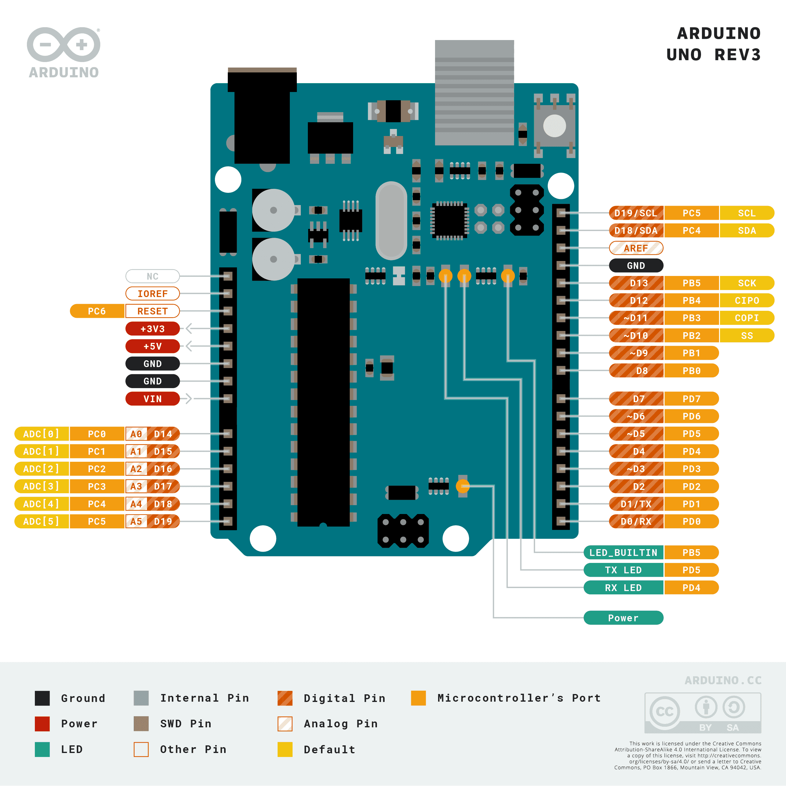
The GPIO pin references for the Uno format are a bit odd. The &arduino_header label is used, but the numbering
starts at the A0 pin and increments as you go counter clockwise around the board. That means the D6 pin
can be referenced by &arduino_header 12 in your overlay files.
ZMK uses the blue color coded pin names to generate devicetree node references. For example, to refer to the pin labeled 17 in the diagram, use &blackpill 17 in the devicetree files.
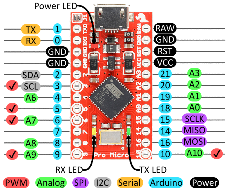
ZMK uses the blue color coded "Arduino" pin names to generate devicetree node references. For example, to refer to the pin labeled 0 in the diagram, use &pro_micro 0 in the devicetree files.
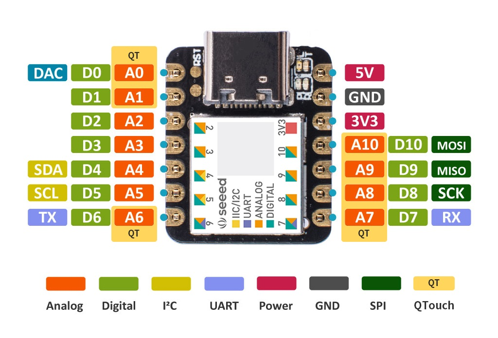
ZMK uses the "D"-prefixed, green color coded pin names, e.g. D2, to generate devicetree node references. For example, to refer to the pin labeled D0 in the diagram, use &xiao_d 0 in the devicetree files.
To use GPIO pins that are not part of the interconnects as described above, you can use the GPIO labels that are specific to each controller type.
For instance, pins numbered PX.Y in nRF52840-based boards can be referred to via &gpioX Y labels.
An example is &gpio1 7 for the P1.07 pin that the nice!nano exposes in the middle of the board.
The Keyboard Scan configuration documentation has the full details on configuring the kscan driver.
- Unibody Keyboard
- Split Keyboard
For a simple 3x3 macropad matrix, the kscan might look something like:
/ {
    kscan0: kscan0 {
        compatible = "zmk,kscan-gpio-matrix";
        diode-direction = "col2row";
        wakeup-source;

        col-gpios
            = <&pro_micro 15 GPIO_ACTIVE_HIGH>
            , <&pro_micro 14 GPIO_ACTIVE_HIGH>
            , <&pro_micro 16 GPIO_ACTIVE_HIGH>
            ;

        row-gpios
            = <&pro_micro 19 (GPIO_ACTIVE_HIGH | GPIO_PULL_DOWN)>
            , <&pro_micro 20 (GPIO_ACTIVE_HIGH | GPIO_PULL_DOWN)>
            , <&pro_micro 21 (GPIO_ACTIVE_HIGH | GPIO_PULL_DOWN)>
            ;
    };
};
For split keyboards you should define your kscan in my_keyboard.dtsi.
If your row-gpios or your col-gpios (or both) are identical between the parts, then they should also be defined in my_keyboard.dtsi.
For example, for a col2row 2-part split keyboard (18 keys split into a 3x3 macropad on both halves) where the "row" GPIOs used are the same for both halves:
/ {
    kscan0: kscan0 {
        compatible = "zmk,kscan-gpio-matrix";
        diode-direction = "col2row";
        wakeup-source;

        row-gpios
            = <&pro_micro 6 (GPIO_ACTIVE_HIGH | GPIO_PULL_DOWN)>
            , <&pro_micro 7 (GPIO_ACTIVE_HIGH | GPIO_PULL_DOWN)>
            , <&pro_micro 8 (GPIO_ACTIVE_HIGH | GPIO_PULL_DOWN)>
            ;

    };
};
The missing col-gpios would be defined in your my_keyboard_left.overlay and my_keyboard_right.overlay files.
#include "my_keyboard.dtsi" // The shared dtsi file is included in the overlay

// Label of the kscan node in the dtsi
&kscan0 {
    col-gpios
        = <&pro_micro 19 GPIO_ACTIVE_HIGH>
        , <&pro_micro 18 GPIO_ACTIVE_HIGH>
        , <&pro_micro 15 GPIO_ACTIVE_HIGH>
        ;
};
#include "my_keyboard.dtsi" // The shared dtsi file is included in the overlay

// Label of the kscan node in the dtsi
&kscan0 {
    col-gpios
        = <&pro_micro 10 GPIO_ACTIVE_HIGH>
        , <&pro_micro 11 GPIO_ACTIVE_HIGH>
        , <&pro_micro 13 GPIO_ACTIVE_HIGH>
        ;
};
Matrix Transform
The matrix transform is used to transform row/column events into "key position" events.
When a key is pressed, a kscan event is generated from it with a row and a column value corresponding to the zero-based indices of the row-gpios and col-gpios pins that triggered the event, respectively.
Then, the "key position" triggered is the index of the RC(row, column) in the matrix transform where row and column are the indices as mentioned above.
This key position will in turn have a behavior binding associated with it in the keymap.
- Unibody Keyboard
- Split Keyboard
The my_keyboard.overlay must include a matrix transform that defines this mapping from row/column values to key positions.
Add #include <dt-bindings/zmk/matrix_transform.h> to the top of the file.
Here is an example of a matrix transform for the previous 3x3 macropad:
#include <dt-bindings/zmk/matrix_transform.h> // Put this with the other includes at the top of your overlay

/ {
    default_transform: keymap_transform0 {
        compatible = "zmk,matrix-transform";
        columns = <3>; // Length of the "col-gpios" array
        rows = <3>; // Length of the "row-gpios" array
        map = <
        //   Key 1 | Key 2 | Key 3
            RC(0,0) RC(0,1) RC(0,2)
        //   Key 4 | Key 5 | Key 6
            RC(1,0) RC(1,1) RC(1,2)
        //   Key 7 | Key 8 | Key 9
            RC(2,0) RC(2,1) RC(2,2)
        >;
    };
};
Split keyboards should define their matrix transform in the shared my_keyboard.dtsi. Add #include <dt-bindings/zmk/matrix_transform.h> to the top of the file.
Here is an example of a matrix transform for the previous example (18-key double macropad):
#include <dt-bindings/zmk/matrix_transform.h> // Put this with the other includes at the top of your dtsi

/ {
    default_transform: keymap_transform0 {
        compatible = "zmk,matrix-transform";
        columns = <6>;
        rows = <3>;
        map = <
        //  LKey 1 |LKey 2 |LKey 3      RKey 1 |RKey 2 |RKey 3
            RC(0,0) RC(0,1) RC(0,2)     RC(0,3) RC(0,4) RC(0,5)
        //  LKey 4 |LKey 5 |LKey 6      RKey 4 |RKey 5 |RKey 6
            RC(1,0) RC(1,1) RC(1,2)     RC(1,3) RC(1,4) RC(1,5)
        //  LKey 7 |LKey 8 |LKey 9      RKey 7 |RKey 8 |RKey 9
            RC(2,0) RC(2,1) RC(2,2)     RC(2,3) RC(2,4) RC(2,5)
        >;
    };
};
The above transform has 6 columns and three rows, while each half of the keyboard only has three columns and three rows. To allow the kscan matrices to be joined in the matrix transform, an offset is applied to the matrix transform of peripherals.
&default_transform { // Offset of 3 because the left side has 3 columns
    col-offset = <3>;
};
This offset means that when the right half of the keyboard has a key event triggered by the GPIO pins at the indices 0,0 of its row-gpios and col-gpios arrays respectively, it will interpret it as an RC(0,3) event rather than an RC(0,0) event.
Additional peripherals would need their columns to be offset by an ever increasing number equal to the sum of the columns in the central + any peripherals that came before it.
You can also apply row offsets with row-offset.
The matrix transform is also used to "correct" pin orderings into something that more closely matches the physical order of keys. Causes of abnormal pin orderings include:
- To reduce the used pins, an "efficient" number of rows/columns for the GPIO matrix is used, that does not match the physical layout of rows/columns of the actual key switches.
- For non-rectangular keyboards with thumb clusters, non
1ulocations, etc.
See the in-tree keyboards that ZMK defines for examples of more complex matrix transformations.
Also see the matrix transform section in the Keyboard Scan configuration documentation for further details and examples of matrix transforms.
Physical Layout
Your keyboard will need to have a physical layout defined. Physical layouts organize the matrix transform, kscan and optionally the physical description of key positions in a single entity.
- Basic
- With ZMK Studio Support
If you are not planning to add support for ZMK Studio, you can add a zmk,physical-layout-compatible node for each physical layout your keyboard supports:
/ {
    physical_layout0: physical_layout_0 { // First physical layout, use different naming for other layouts
        compatible = "zmk,physical-layout";
        display-name = "Default Layout";
        kscan = <&kscan0>; // Label of the kscan node, optional if all layouts use the same
        transform = <&default_transform>; // Label of the matrix transform for this layout
    };
};
These nodes should be placed in my_keyboard.overlay for unibody keyboards and the shared my_keyboard.dtsi for splits.
If you are planning to add support for ZMK Studio, you should follow the physical layouts documentation to create a new file my_keyboard-layouts.dtsi which includes the physical layout definitions.
Once you have finished defining your physical layouts, import the my_keyboard-layouts.dtsi file at the top of your my_keyboard.overlay file (unibody) or my_keyboard.dtsi file (split).
#include "my_keyboard-layouts.dtsi"
Chosen Node
Set the chosen node to a defined "default" physical layout. This should also be placed in the same file as the physical layout, i.e. my_keyboard.overlay for unibodies and my_keyboard.dtsi for split keyboards.
/ {
    chosen {
        zmk,physical-layout = &physical_layout0;
        // Other chosen items
    };
};
If you define multiple physical layouts, users can select a different layout by overriding the zmk,physical-layout chosen node in their keymap file or by using ZMK Studio if your board is compatible with it.
If all of your physical layouts use the same kscan node under the hood, you can skip setting the kscan property on each layout and instead assign the zmk,kscan chosen node to your single kscan instance:
/ {
    chosen {
        zmk,kscan = &kscan0;
        zmk,physical-layout = &physical_layout0;
        // Other chosen items
    };
};
Wired Split
- Unibody Keyboard
- Split Keyboard
If testing the experimental wired split support, you should assign a predefined or pinctrl configured UART to the device property of a new node with compatible value of "zmk,wired-split":
/ {
    wired_split {
        compatible = "zmk,wired-split";
        device = <&pro_micro_serial>;
    };
};
See the wired split configuration for more details.
For wireless split keyboards, this step should be skipped, especially since the UART pins on your controller might already be in use for other functionality.
Default Keymap
Each keyboard should provide a default keymap to be used when building the firmware, which can be overridden and customized by user configs.
For "shield keyboards", this should be placed in the boards/shields/my_keyboard/my_keyboard.keymap file.
Here is an example simple keymap for a 3x3 macropad, with only one layer:
#include <behaviors.dtsi>
#include <dt-bindings/zmk/keys.h>

/ {
    keymap {
        compatible = "zmk,keymap";

        default_layer { // Layer 0
            // -------------------------------------
            // |     Z     |     M     |     K     |
            // |     A     |     B     |     C     |
            // |     D     |     E     |     F     |
            bindings = <
                &kp Z    &kp M    &kp K
                &kp A    &kp B    &kp C
                &kp D    &kp E    &kp F
            >;
        };
    };
 };
The keymap should match the order of the keys in the matrix transform exactly, left to right, top to bottom (they are both 1 dimensional arrays rearranged with newline characters for better legibility). See Keymaps for information on defining keymaps in ZMK. If you wish to use ZMK Studio with your keyboard, make sure to assign the ZMK Studio unlocking behavior to a key in your keymap.
Metadata
ZMK makes use of an additional metadata YAML file for all boards and shields to provide high level information about the hardware to be incorporated into setup scripts/utilities, website hardware list, etc.
Here is a sample corne.zmk.yml file from the repository:
file_format: "1"
id: corne
name: Corne
type: shield
url: https://github.com/foostan/crkbd/
requires: [pro_micro]
exposes: [i2c_oled]
features:
  - keys
  - display
siblings:
  - corne_left
  - corne_right
You should place a properly named my_keyboard.zmk.yml file in the directory next to your other shield values, and fill it out completely and accurately.
See Hardware Metadata Files for the full details.
Testing
Once you've defined everything as described above, you can build your firmware to make sure everything is working. If you wish to test that your keyboard works with ZMK Studio, you'll also need to follow the instructions for enabling Studio.
GitHub Actions
To use GitHub Actions to test, push the files defining the keyboard to GitHub.
Next, update the build.yaml of your zmk-config to build your keyboard.
- If your shield is defined in your
zmk-config, then the shield should start building. - If the shield is defined in a separate module, you will need to adjust your
west.ymlto reference the module.
Local Toolchain
You can also use a local toolchain setup to test your keyboard. Follow our guide for getting set up, then follow the instructions for building and flashing locally. You will need to specify the module of your keyboard when building.