Board Pin Control
This page exists to provide a guide to Pin Control for ZMK users and designers. Refer to Zephyr's page on Pin Control for elaboration and more details on any of the points raised here.
A basic keyboard design as introduced in the new shield guide only uses its pins for the keyboard matrix. Many keyboard designs make use of advanced components or functionality, such as displays or shift registers. This results in the keyboard making use of communication protocols such as (but not limited to) SPI, I2C, or UART. Configuring pins for the usage of advanced functionality such as drivers for the previously named protocols is referred to as "Pin Control".
The details of pin control can vary from vendor to vendor. An attempt was made to be as general as possible, but it isn't possible to cover all possible cases. The approaches for the nRF52840 and RP2040 MCUs/SoCs are documented in their entirety below. For other MCUs/SoCs, please refer to the Zephyr documentation and the examples and other files found in-tree of ZMK and ZMK's fork of Zephyr.
Boards, Shields, and Modules
Pin control is always defined for a board, never for a shield:
- If you are defining a keyboard that is a board, then you will be editing and adding on to the files in your keyboard's folder as usual.
- If your keyboard consists of a board and a shield, then you should define a new folder inside of your shield's folder called
boards. You will need to add a<board>.overlayfor each board to be used with said shield. Take for example the file structure of the "sofle" shield:Note that you will need to define a separate overlay for each of the boards to be used with the shield.boards/shields/sofle/
├── boards/
│ ├── nice_nano_nrf52840_zmk.overlay
│ ├── nrfmicro_nrf52840_zmk_1_3_0.overlay
└── <sofle shield defining files>
Assume that the shield that you are using is found in-tree of ZMK or within an external module, and does not contain the overlay for the board that you wish to use. If this is the case, then you should fork the source repository and add the overlay to the fork. Use said fork to build your firmware, and potentially submit a PR to upstream.
Predefined Nodes
Many boards will already have some pins configured for particular protocols. We recommend using these pins whenever possible.
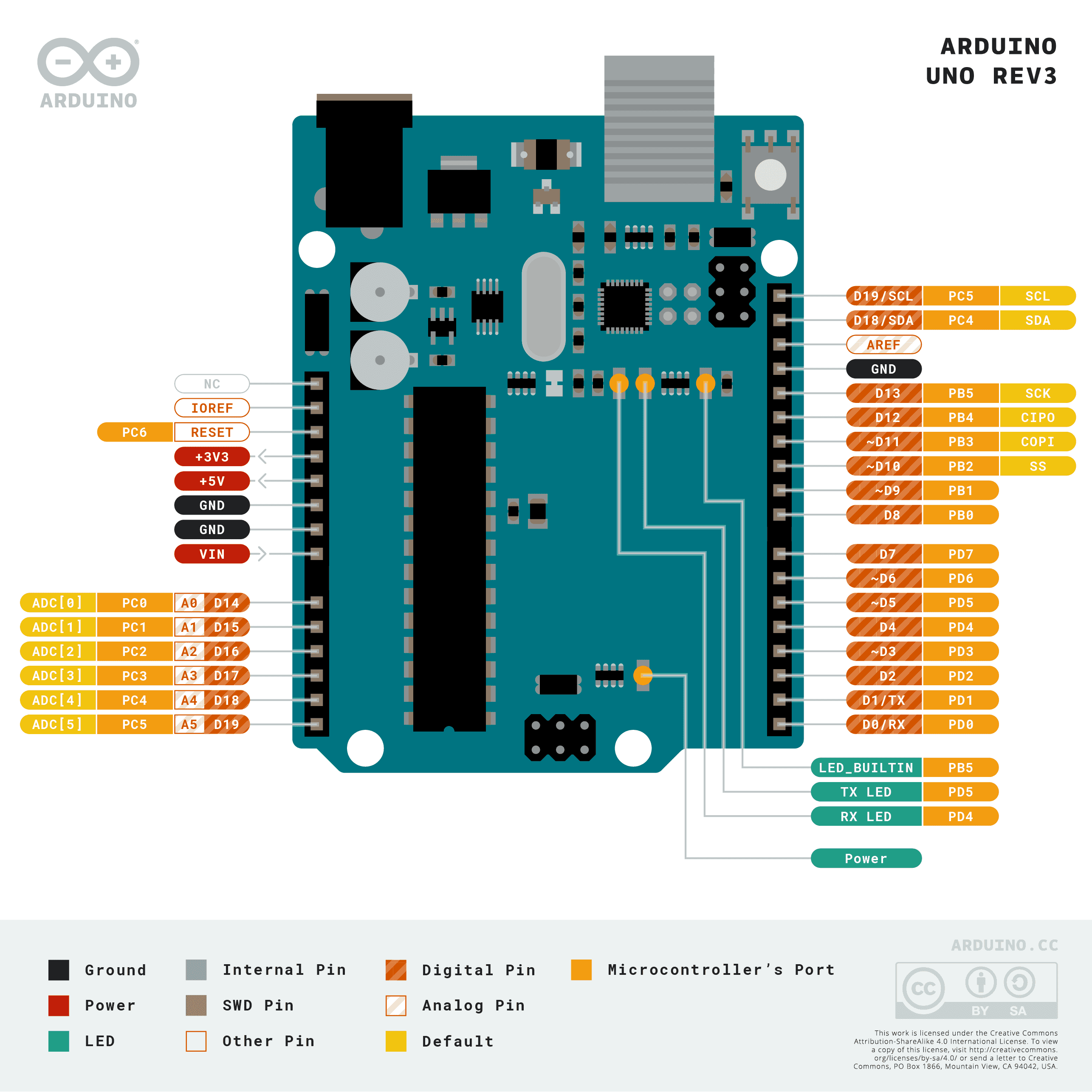
- Arduino Uno Rev3 Shields
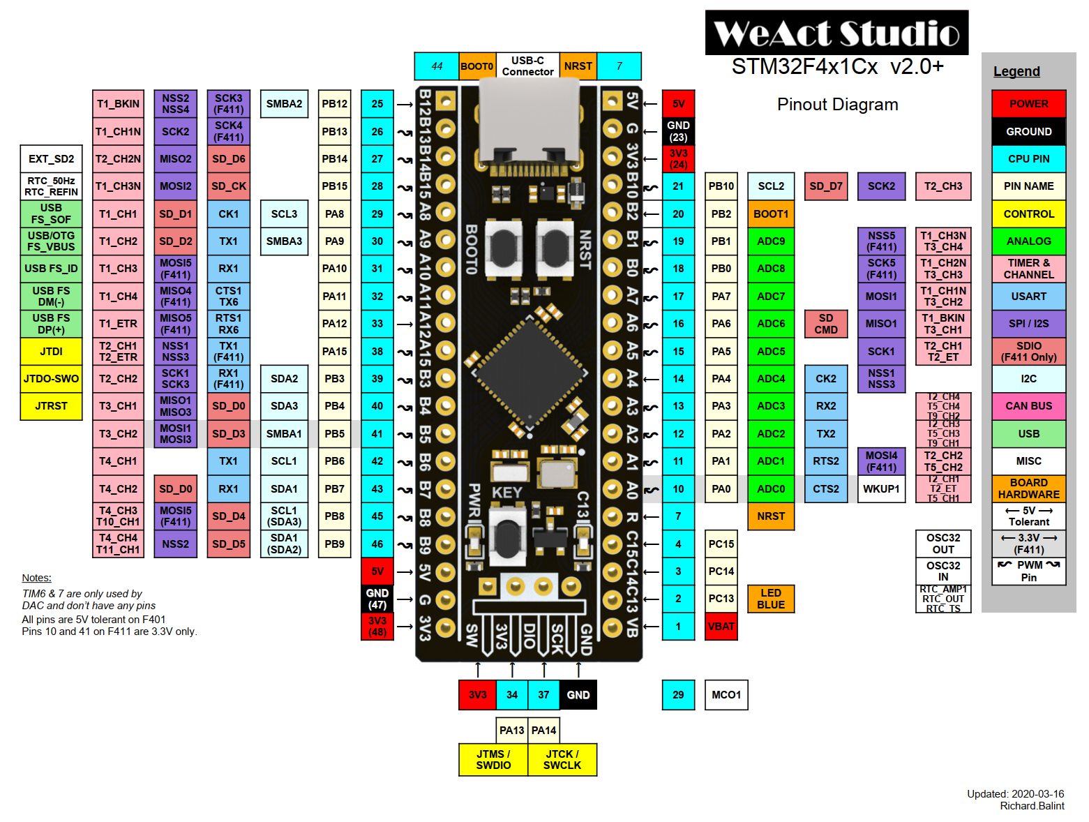
- BlackPill Shields
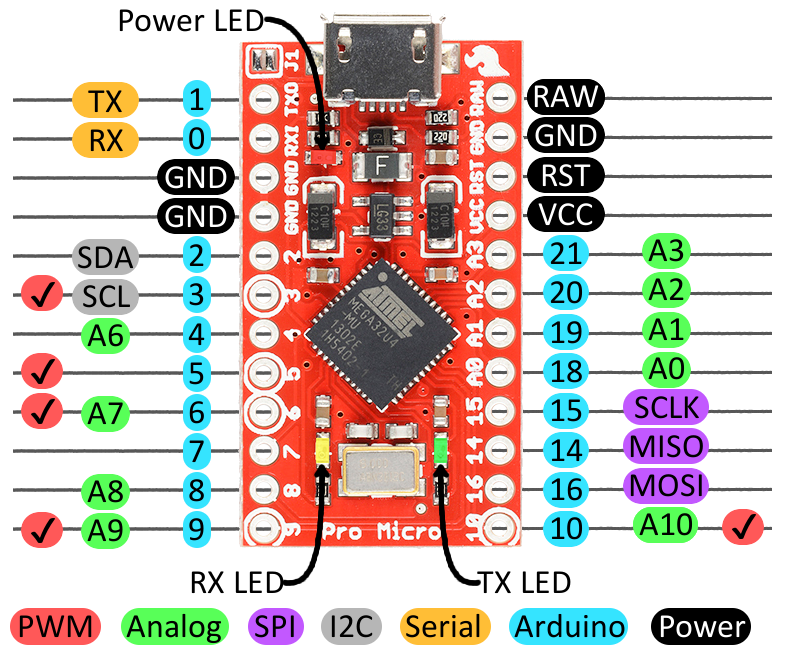
- Pro Micro Shields
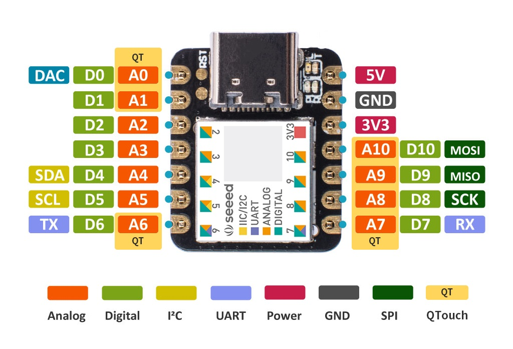
- Seeed XIAO Shields

The following node labels are available:
- I2C bus:
&arduino_i2c - SPI bus:
&arduino_spi - UART:
&arduino_serial - ADC:
&arduino_adc

The following node labels are available:
- I2C bus:
&blackpill_i2c - SPI bus:
&blackpill_spi - UART:
&blackpill_serial

The following node labels are available:
- I2C bus:
&pro_micro_i2c - SPI bus:
&pro_micro_spi - UART:
&pro_micro_serial

The following node labels are available:
- I2C bus:
&xiao_i2c - SPI bus:
&xiao_spi - UART:
&xiao_serial
Note that some boards may have these pins configured to fit the above pinouts, rather than the capabilities of the MCU. Most notably, boards using the nRF52840 often end up putting low-frequency pins at the locations of the SPI buses above. More on low-frequency pins in the next section.
Pin Selection
Prior to setting up pin control, you will want to make sure that the pins you use are suitable for the driver that you are using. For this purpose, you will most likely need to consult the datasheet of your MCU/SoC directly. Different MCUs/SoCs have different restrictions in regards to this. The nRF52840 and RP2040 are excellent examples:
- The nRF52840 has its pins marked as either low frequency or high frequency.
- Using low frequency pins at a frequency of over 10KHz can cause reliability issues with the wireless antenna, making them unideal for I2C, UART, and (most of) SPI.
- High frequency pins can be used for almost all protocols that the nRF52840 is capable of, without restrictions. The exception is QSPI, which is restricted to specific high frequency pins (QSPI is mostly irrelevant for keyboard designs).
- The RP2040 supports two SPI buses labeled SPI0 and SPI1, two I2C buses labeled I2C0 and I2C1, and two UART buses labeled UART0 and UART1. It restricts its pins to particular functions for each of these. For example, pin 0 can be used as the RX pin of SPI0, the TX pin of UART0, or the SDA pin of I2C0.
You will need to make sure that the pins you select all lie on the same bus and fulfil each of the functions necessary for the bus to function. So for a fully functioning SPI0 bus, you would need to select a SPI0 RX pin, a SPI0 TX pin, and a SPI0 SCK pin.
The RP2040 also comes with programmable input/output blocks (PIO) that can be used to emulate protocols such as (but not limited to) the previously named protocols. Using PIO adds some complexity though, and there are a limited number of PIO blocks, so it is recommended that you stick to the predefined buses where possible.
Note that not all peripherals require all pins to be defined - for example, there are plenty of SPI devices which do not require either the MISO (Main In, Sub Out) or the MOSI (Main Out, Sub In) pin.
Pin Control File
Pin control consists of two parts:
- Defining and grouping the pins together for a driver
- Augmenting a driver/bus node and assigning pin groups to it
It is standard to do this in two separate files. Create a file called <my-board>-pinctrl.dtsi, which will be used for the first part. This file will later be imported into your board's .dts. If you are configuring pin control for a shield, it is common to write the contents of both parts into the .overlay file directly.
MCU/SoC Pinctrl Bindings Files
The specifics of pin control for a particular MCU/SoC are presented via a devicetree bindings file, found under zephyr/dts/bindings/pinctrl/.
- The nRF52840 uses the
zephyr/dts/bindings/pinctrl/nordic,nrf-pinctrl.yamlfile. - The RP2040 uses the
zephyr/dts/bindings/pinctrl/raspberrypi,pico-pinctrl.yamlfile.
These files often contain useful comments on pin control for their devices, and so can be worth a read in addition to this page.
MCU/SoC Pinctrl Bindings Headers
MCUs/SoCs will also have pinctrl header files found under zephyr/include/zephyr/dt-bindings/pinctrl/. You will want to make sure that the header file corresponding to your MCU/SoC is imported into your board's .dts/.overlay. For the nRF52840, your board should already be importing a file such as nordic/nrf52840_qiaa.dtsi, which includes the pinctrl header via the following inclusions:
nrf-pinctrl.h -> nrf_common.dtsi -> nrf52840.dtsi -> nrf52840_qiaa.dtsi
The corresponding file for the RP2040 (rpi_pico/rp2040.dtsi), however, does not include the pinctrl header. Hence you will need to import said header at the top of your <my-board>-pinctrl.dtsi file:
#include <dt-bindings/pinctrl/rpi-pico-rp2040-pinctrl.h>
If you are configuring pin control for a shield, then this file may already be imported by the board's definition, in which case you shouldn't re-include it here.
Some MCUs/SoCs may have their headers located in a Zephyr HAL module. See for example the Atmel HAL module.
Pinctrl Node
All of your configuration will happen by adjusting the pinctrl node. Changes are made like so:
&pinctrl {
    /* your modifications go here */
};
Within said node, you will configure one or more child nodes for the buses. You will want to define the child nodes according to the instructions in the pinctrl.yaml file.
The child nodes that you define should be named appropriately. The common naming schema is usageNumber_state. For example, uart0_default.
Child nodes are (generally, there are exceptions) expected to contain one or more subnodes typically named "groupX". These are for grouping together pins that should be assigned the same state, such as enabling an internal pull-up.
Below are some examples of SPI child nodes for the nRF52840 and the RP2040. Further examples are contained within the comments of the respecting pinctrl.yaml files.
- nRF52840
- RP2040
&pinctrl {
    /* configuration for spi0 device, default state */
    spi0_default: spi0_default {
        /* node name is arbitrary */
        group1 {
            /* main role: configure P0.01 as SPI clock, P0.02 as SPI MOSI, P0.03 as SPI MISO */
            psels = <NRF_PSEL(SPIM_SCK, 0, 1)>,
                    <NRF_PSEL(SPIM_MOSI, 0, 2)>,
                    <NRF_PSEL(SPIM_MISO, 0, 3)>;
        };
    };

    /* configuration for spi0 device, sleep state */
    spi0_sleep: spi0_sleep {
        group1 {
            /* main role: configure P0.01 as SPI clock, P0.02 as SPI MOSI, P0.03 as SPI MISO */
            psels = <NRF_PSEL(SPIM_SCK, 0, 1)>,
                    <NRF_PSEL(SPIM_MOSI, 0, 2)>,
                    <NRF_PSEL(SPIM_MISO, 0, 3)>;
            low-power-enable;
        };
    };

};
Pins are always selected via assignments to psels. NRF_PSEL is a helper macro with the following arguments:
- Pin function configuration. This is the
nameportion of one of theNRF_FUNC_{name}macros found inzephyr/include/zephyr/dt-bindings/pinctrl/nrf-pinctrl.h. - Port (0 or 1).
- Pin (0 to 31).
The following pin properties can be assigned to groups:
bias-disable: Disable pull-up/down (default behavior, not required).bias-pull-up: Enable pull-up resistor.bias-pull-down: Enable pull-down resistor.low-power-enable: Configure pin as an input with input buffer disconnected.
Note that bias options are mutually exclusive.
There is an additional child node for the "sleep" state, configuring the pins for low power. More on states will be explained later.
&pinctrl {
    /* configuration for spi0 device, default state */
    spi0_default: spi0_default {
        group1 {
            /* configure P18 as SPI0 clock, P19 as SPI0 MOSI */
            pinmux = <SPI0_SCK_P18>, <SPI0_TX_P19>;
        };
        group2 {
            /* configure P16 as SPI0 MISO */
            pinmux = <SPI0_RX_P16>;
            /* enable input on pin 1 */
            input-enable;
        };
    };

    /* configuration for an spi device using PIO0, default state  */
    pio0_spi_default: pio0_spi_default {
        group1 {
            /* Configure P13 and P14 for PIO, to be used for MOSI and SCK */
            pinmux = <PIO0_P13>, <PIO0_P14>;
        };
        group2 {
            /* Configure P16 for PIO to be used for MISO with input */
            pinmux = <PIO0_P12>;
            input-enable;
        };
    };
};
The values that can be listed in pinmux to assign functionality to pins are listed in zephyr/include/zephyr/dt-bindings/pinctrl/rpi-pico-rp2040-pinctrl.h.
The following pin properties can be assigned to groups:
bias-disable: Disable pull-up/down (default, not required).bias-pull-up: Enable pull-up resistor.bias-pull-down: Enable pull-down resistor.input-enable: Enable input from the pin.input-schmitt-enable: Enable input hysteresis.drive-strength: Set the drive strength of the pin, in milliamps. Possible values are: 2, 4, 8, 12 (default: 4mA)slew-rate: If set to 0, slew rate is set to slow. If set to 1, it is set to fast.
Driver/Bus Node
Once pin control for a driver/bus has been defined, you'll need to adjust another node defining the driver/bus. This adjustment can be done in a number of places by convention:
- If defining a unique board,
<board>.dts - If defining boards with multiple revisions/versions that share pin control,
<board>-common.dtsi(which is then included by each<board>_<revision>.dtsi) - If configuring boards for a shield, directly in the
<board>.overlayfile
You'll want to identify the correct node for you to be changing. The nRF52840 has nodes defined in dts/arm/nordic/nrf52840.dtsi, while the RP2040 has nodes defined in dts/arm/rpi_pico/rp2040.dtsi. Always be aware of and account for other devices on your node, there may be some which you did not add yourself.
Adjust the node like so:
- nRF52840
- RP2040
&spi0 {
    compatible = "nordic,nrf-spim";
    pinctrl-0 = <&spi0_default>;
    pinctrl-1 = <&spi0_sleep>;
    pinctrl-names = "default", "sleep";
};
&spi0 {
    pinctrl-0 = <&spi0_default>;
    pinctrl-names = "default";
};
This assigns the pins defined in the previous section's examples to the spi0 node.
Notice that the nRF52840 assigns two items. This is because nodes making use of pin control come with two states by default (though they can have more), a default state and a sleep state. The nRF52840 can put pins into a "low power state", to reduce power consumption while on sleep. If the RP2040 node made use of pullup or pulldown resistors which had a risk of power leakage while asleep, then it would also define an additional pinctrl child node and assign it like in the nRF52840 example.
The nRF52840 example also changes the compatible assignment to use SPIM rather than SPI, since it is taking on the "main" role. Check the datasheet for more information about SPIM. The RP2040 makes no such distinction.
Alias
You may wish to provide an alias to the node for various reasons:
- Compatibility with other boards, if defining for a shield
- Compatibility with an interconnect
- Easier personal use
Aliases are assigned like so:
my_alias_spi: &spi0 {};
Usage
Once you have defined your node, you make use of it by further adjusting the node. You will most likely need to enable the node, as most nodes come disabled:
&spi0 {
    status = "okay";
};
You would then want to make any adjustments to the node that are necessary, for example adjusting the clock speed. See the Zephyr API documentation for your compatible property to see the available properties for customisation. It is recommended to read through the description of important properties, potentially with the addition of this blog post if #address-cells is confusing you.
For SPI specifically, you would create a child node within your SPI bus for each device making use of the SPI bus.
&spi0 {
    cs-gpios = <&gpio0 15 GPIO_ACTIVE_LOW>, <&gpio0 17 GPIO_ACTIVE_LOW>;
    device1: device@0 {
        compatible = "manufacturer,device";
        reg = <0>;
        spi-max-frequency = <1000000>; /* conservatively set to 1MHz */
    };
    device2: device@1 {
        compatible = "manufacturer,device";
        reg = <1>;
        spi-max-frequency = <1000000>; /* conservatively set to 1MHz */
    };
};
Additional information on configuring specific devices for use with SPI buses or similar can be found in other pages of the ZMK documentation, or in the Zephyr documentation.
RP2040 PIO
The previous RP2040 example also configured pins for use with an RP2040 PIO block. To use PIO with SPI (or another purpose) you'll need to adjust the pio0 or pio1 nodes as follows:
#include "<board>-pinctrl.dtsi"

&pio0 {
    /* enables this PIO block */
    status = "okay";
    pio0_spi: pio0_spi {
        /* Assign pinctrl to node */
        pinctrl-0 = <&pio0_spi_default>;
        pinctrl-names = "default";
        compatible = "raspberrypi,pico-spi-pio";
        #address-cells = <1>;
        #size-cells = <0>;
        clocks = <&system_clk>;
        clock-frequency = <4000000>;
        /* These pins should be the same as in pinctrl */
        miso-gpios = <&gpio0 12 0>;
        clk-gpios = <&gpio0 14 GPIO_ACTIVE_HIGH>;
        mosi-gpios = <&gpio0 15 GPIO_ACTIVE_HIGH>;

        cs-gpios = <...>; // List of chip select gpios, one for each device
        /* Nodes using the bus go here */
    };
};
Depending on the desired usage for PIO, you will want to adjust the compatible property and the SPI-specific properties (miso-gpios, clk-gpios, mosi-gpios). See the Zephyr API documentation for information about alternative PIO drivers. Once defined, SPI can be used via PIO as presented in the previous subsection, referring to pio0_spi (or similar) instead of spi0.
Additional examples
Below are examples for UART and I2C, as the other two most common usages for pin control.
UART nRF52840
In the pin control file:
&pinctrl {
    /* configuration for uart0 device, default state */
    uart0_default: uart0_default {
        group1 {
            /* configure P0.1 as UART_TX and P0.2 as UART_RTS */
            psels = <NRF_PSEL(UART_TX, 0, 1)>, <NRF_PSEL(UART_RTS, 0, 2)>;
        };
        group2 {
            /* configure P0.3 as UART_RX and P0.4 as UART_CTS */
            psels = <NRF_PSEL(UART_RX, 0, 3)>, <NRF_PSEL(UART_CTS, 0, 4)>;
            /* both P0.3 and P0.4 are configured with pull-up */
            bias-pull-up;
        };
    };

    uart0_default: uart0_default {
        group1 {
            psels = <NRF_PSEL(UART_TX, 0, 22)>, // EXT1
                    <NRF_PSEL(UART_RX, 0, 21)>; // EXT2
        };
    };

    uart0_sleep: uart0_sleep {
        group1 {
            /* configure P0.1 as UART_TX and P0.2 as UART_RTS */
            psels = <NRF_PSEL(UART_TX, 0, 1)>, <NRF_PSEL(UART_RTS, 0, 2)>;
            low-power-enable;
        };
        group2 {
            /* configure P0.3 as UART_RX and P0.4 as UART_CTS */
            psels = <NRF_PSEL(UART_RX, 0, 3)>, <NRF_PSEL(UART_CTS, 0, 4)>;
            /* both P0.3 and P0.4 are configured with pull-up */
            bias-pull-up;
            low-power-enable;
        };
    };
};
In the main file:
#include "<board>-pinctrl.dtsi"

&uart0 {
    pinctrl-0 = <&uart0_default>;
    pinctrl-1 = <&uart0_sleep>;
    pinctrl-names = "default", "sleep";
};
On designs using wired split on nRF52840, using asynchronous UART APIs with DMA will help ensure that the interrupts used to handle timing sensitive BT interactions can respond when needed.
This can be accomplished by overwriding the compatible property to "nordic,nrf-uarte", e.g.:
&uart0 {
    compatible = "nordic,nrf-uarte";
    pinctrl-0 = <&uart0_default>;
    pinctrl-1 = <&uart0_sleep>;
    pinctrl-names = "default", "sleep";
};
In addition to this compatible override, a setting needs to be tweaked to ensure that the UART isn't selected for interrupt mode when async is prefered.
The following should be added to the board's/shield's Kconfig.defconfig:
config UART_0_INTERRUPT_DRIVEN
    depends on !ZMK_SPLIT_WIRED_UART_MODE_ASYNC
for the correct UART_# prefix matching the numbered UART being used.
UART rp2040
In the pin control file:
#include <dt-bindings/pinctrl/rpi-pico-rp2040-pinctrl.h>

&pinctrl {
    /* configuration for the usart0 "default" state */
    uart0_default: uart0_default {
        group1 {
            /* configure P0 as UART0 TX */
            pinmux = <UART0_TX_P0>;
            };
        group2 {
            /* configure P1 as UART0 RX */
            pinmux = <UART0_RX_P1>;
            /* enable input on pin 1 */
            input-enable;
        };
    };
};
In the main file:
#include "<board>-pinctrl.dtsi"

&uart0 {
    pinctrl-0 = <&uart0_default>;
    pinctrl-names = "default";
};
UART RP2040 PIO
In the pin control file:
#include <dt-bindings/pinctrl/rpi-pico-rp2040-pinctrl.h>

&pinctrl {
    /* configuration for the uart0 "default" state */
    pio0_uart_default: pio0_uart_default {
        /* tx pin, NAME IS NOT ARBITRARY */
        tx_pins {
            /* configure P0 as UART0 TX */
            pinmux = <PIO0_P0>;
            };
        /* rx pin, NAME IS NOT ARBITRARY */
        rx_pins {
            /* configure P1 as UART0 RX */
            pinmux = <PIO0_P1>;
            /* enable input on pin 1 */
            input-enable;
            bias-pull-up;
        };
    };
};
In the main file:
#include "<board>-pinctrl.dtsi"

&pio0 {
    status = "okay";

    pio0_uart: serial {
        status = "okay";
        compatible = "raspberrypi,pico-uart-pio";
        pinctrl-0 = <&pio0_uart_default>;
        pinctrl-names = "default";
        current-speed = <115200>;
    };
};
I2C nRF52840
Specifically for an I2C controller, aka Nordic TWIM.
In the pin control file:
&pinctrl {
    /* configuration for i2c0 device, default state */
    i2c0_default: i2c0_default {
        group1 {
            psels = <NRF_PSEL(TWIM_SDA, 0, 7)>,
                <NRF_PSEL(TWIM_SCL, 0, 27)>;
        };
    };

    i2c0_sleep: i2c0_sleep {
        group1 {
            psels = <NRF_PSEL(TWIM_SDA, 0, 7)>,
                <NRF_PSEL(TWIM_SCL, 0, 27)>;
            low-power-enable;
        };
    };
};
In the main file:
#include "<board>-pinctrl.dtsi"

&i2c0 {
    compatible = "nordic,nrf-twim"; // I2C controller instead of generic
    status = "okay";
    pinctrl-0 = <&i2c0_default>;
    pinctrl-1 = <&i2c0_sleep>;
    pinctrl-names = "default", "sleep";
    clock-frequency = <I2C_BITRATE_FAST>;

    /* Nodes using the bus go here */
};
I2C RP2040
In the pin control file:
#include <dt-bindings/pinctrl/rpi-pico-rp2040-pinctrl.h>

&pinctrl {
    /* configuration for the i2c0 "default" state */
    i2c0_default: i2c0_default {
        group1 {
            pinmux = <I2C0_SDA_P4>, <I2C0_SCL_P5>;
            input-enable;
            input-schmitt-enable;
        };
    };
};
In the main file:
#include "<board>-pinctrl.dtsi"

&i2c0 {
    status = "okay";
    pinctrl-0 = <&i2c0_default>;
    pinctrl-names = "default";
    clock-frequency = <I2C_BITRATE_STANDARD>;

    /* Nodes using the bus go here */
};
I2C RP2040 PIO
Zephyr currently does not have support for I2C using RP2040 PIO.